Water/Wastewater
Possible reasons for flowmeter failure during installation
Jul 18 2023
“Why has my pulse flow meter sensor failed?”
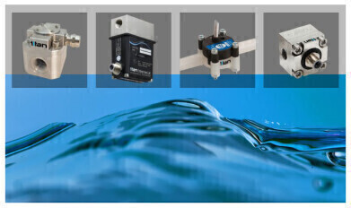
A majority of flow meters with a pulse output utilise a rotating element with internal magnets; these magnets activate a solid-state sensor to give a pulse output proportional to the liquid flow rate.
Titan Enterprises Ltd, have four decades of experience in the design, development and manufacture of flow meter technology, here they explain some of the reasons why sensors may fail and the appropriate action that will prevent damage that leads to costly repairs and process downtime.
Titan tends to use high-quality Hall effect sensors within their pulse precision flow measurement instruments. These sensors operate between 4.0Vdc and 30Vdc, however, there are a few situations that will cause turbine and oval gear flow meters failure:
- Incorrect wiring: Installer must take great care when wiring the sensor power supply and pulse output of the flowmeter; sensors are unable to cope with faulty wiring -
The sensor will fail suddenly, completely and permanently in cases of reverse polarity or short circuits.
- Unregulated power supply: Exceeding the maximum 30Vdc to the Hall Effect sensor will cause damage to the device, therefore a high-quality, regulated DC power supply is strongly recommended for powering a pulse flow meter.
Electrical interference and/or voltage spikes: Connected equipment containing inductors (or coils), or electromagnetic components – for example: solenoid valves or pumps - may produce high voltage spikes when switching. These spikes can be anywhere between a hundred to thousands of volts; if this is on the same circuit, it will irreparably damage the flowmeter’s sensor. Electrical interference also occurs even without a direct connection if cabling is routed too close to high-power equipment.
A ubiquitous failure mode is where a standard solenoid valve is operated on the same power supply as the flowmeter. The solenoid de-energises in 1 ms resulting in a spike of 100s of volts. Some of this spike feeds through to the sensor, therefore momentarily exceeding the maximum of 30Vdc considerably and therefore causing it to fail.
What actions can be taken to avoid catastrophic failures in flow measuring systems?
Neil Hannay, Titan Enterprises’ Senior R&D Engineer comments: “The majority of damage tends to be caused during the installation of the flowmeter. Minor errors can result in a non-operational meter before the customer has even started, leading to costly repairs or replacements, as well as process downtime, that can be avoided.”
Titan Enterprises produce more than 70,000 flowmeters annually; these are used in many different industries, processes and applications, so the need for troubleshooting and problem-solving for customers is a regular occurrence, especially for users who are less familiar with Titan’s flow metering range.
Neil added: “Titan provides written data and instruction sheets with all our flow meters, and we have also published some installation tutorial videos to help our customers and prevent any miswiring that can damage the units.”
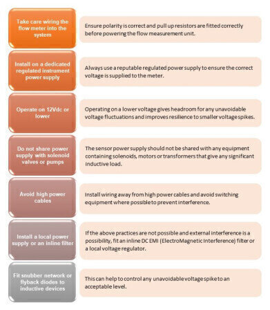
The installation checklist will help significantly to prevent the most common causes of pulse flow meter sensor failure. Please view the second image above.


Digital Edition
AET 28.2 April/May 2024
May 2024
Business News - Teledyne Marine expands with the acquisition of Valeport - Signal partners with gas analysis experts in Korea Air Monitoring - Continuous Fine Particulate Emission Monitor...
View all digital editions


Events
Jul 30 2024 Jakarta, Indonesia
China Energy Summit & Exhibition
Jul 31 2024 Beijing, China
2024 Beijing International Coal & Mining Exhibition
Aug 07 2024 Beijing, China
IWA World Water Congress & Exhibition
Aug 11 2024 Toronto, Canada
Aug 25 2024 Stockholm, Sweden and online