Water/Wastewater
Determination of Flow Rates in part-filled Applications using the Radar Method
Aug 18 2017
Author:
Mathias Stratyla
on behalf of Nivus GmbHThe radar measurement method plays an increasingly important role in the water and wastewater field. This is particularly reflected by the “Metering outside of the medium” trend. Flow measurement using radar which enables contactless measurements thus becomes a major focal point. It features a wide range of applications and hence is useful as permanent measurement system for many applications with part filled pipes or canals in the water and wastewater field.
Flow Rate Determination
The determination of flow rates is indispensable for many processes when it comes to monitor water or wastewater volumes. In order to ensure continuous flow determination, however, a measurement system is required which enables optimum velocity detection for the according application. The radar measurement method allows contactless flow velocity metering. Therefore it is ideal for applications with strong sedimentation on the channel bottom or if sensors cannot be installed on the channel bottom or within the medium due to several reasons. In contrast to other measurement systems radar metering entails the advantage that it is largely independent from the properties of the measurement medium such as conductivity, density, temperature or viscosity. Moreover the microwave-based method stands out from the crowd of other flow measurement methods due to low maintenance and easy installation.
Measurement Principle
Radar sensors are installed outside of or above the measurement medium. The radar sensor sends out a signal with a certain frequency. The signal is reflected as soon as it impinges on the water surface. A frequency shift is induced once the signal is reflected from the water surface. The reflected signal is detected by the radar sensor and will be evaluated by using the Doppler principle.
Image: Schematic drawing: Radar measurement principle
The precondition for the radar method is wave formation on the water surface. The sensor measures the movement of the waves and hence the surface velocity of the water. On the water surface a single velocity is measured selectively. With the aid of the hydraulic COSP model developed by NIVUS it is possible to compute the average flow velocity from the selective single velocity. The flow level is measured by utilising an extra level sensor which enables to determine the wetted area A. Flow Q is calculated from the average velocity V and the wetted area A as follows:
Q= V x A
Q = Flow rate
= Average velocity
A = Wetted area
Formula 1: General flow rate calculation
Radar Technologies
A distinction is made between pulse radar units and continuous wave radar units. Pulse radar units emit high-frequency impulse signals at high power. Once reflected, the radar sensor receives the signal as echo. New signals will not be transmitted before an echo has been received. Continuous-wave radar units (abbreviation: CW radar units) transmit continuous signals. Reflected signals are hence received permanently which permits to permanently measure velocities e.g. in the water and wastewater field. Utilising the radar technology NIVUS rely on the latter method for flow measurement.
Radar Meter System
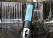
The standard radar metering system comprises a radar flow velocity sensor (optionally with Ex zone 1 approval), a level sensor and the new NivuFlow 550 transmitter. Both sensors provide the measured data for the transmitter which in turn computes the flow Q by considering hydraulic models.
Photos: Complete radar measurement system: OFR radar sensor, level sensor type i-Series (left) and NivuFlow 550 transmitter
Installation and system set-up can be carried out quick and easy since all measurement place parameters can be set directly on the transmitter. Extra software or hardware are not required.
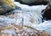
In a WWTP inlet sewer flow volume as well as flow velocity were to be determined and logged. The measurement serves as control measurement to avoid flooding the treatment plant. The customer demanded a contactless low-maintenance system due to partially high dirt loads and thus sedimentation were expected on the channel bottom. Due to this installing e. g. water-ultrasonic sensors on the channel bottom was not desired. A radar meter was the most suitable measurement system for this measurement site since all requirements were met: an easy-to-install contactless measurement system.
Photo: Application example WWTP inlet sewer
Hybrid Flow Measurement
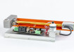
Apart from pure radar meter systems, NIVUS is the only provider to offer a hybrid measurement system for flow measurement. This hybrid system represents an extension of the radar measurement system. Besides flow velocity detection using radar the flow velocity is additionally detected by using ultrasonic cross correlation. The measurement system is therefore equipped with two flow velocity sensors, one level sensor and the NivuFlow 7550 hybrid transmitter.
Photos: Hybrid measurement system: v-sensor 1 OFR radar sensor, level sensor i-Sensor, v-sensor 2 POA sensor, NivuFlow 7550 hybrid transmitter
The transmitter combines or completes the measured flow velocities obtaining the average flow velocity. Depending on the sensor installation positions and the filling level there are two basic applications for hybrid meter system: hybrid metering as extended measurement range e. g. during flood conditions and hybrid metering as redundant measurement to increase accuracy.
Extended Measurement Range: Flood Sensor
Standard discharge measurement situation:
The ultrasonic wedge sensor is fastened on the pipe ceiling. In this system configuration normally only the radar sensor measures the flow velocity.
Image: Hybrid measurement system; Standard discharge measurement situation
High Level Measurement Situation:
The ultrasonic sensor which is installed slightly out of the channel crest begins to measure shortly before the flood situation is reached depending on the installation point. In this case, the ultrasonic sensor as well as the radar sensor measure parallel. The example shown here (see below) has a very small measurement range since the ultrasonic sensor is fastened to the ceiling and begins to measure only shortly before the dead zone of the radar sensor is reached. Based on the local flow velocities detected by the ultrasonic sensor the hydraulic model can be optimised for the entire measurement situation.
Flood Measurement Situation:
Measuring with the radar sensor is not possible any more once the sensor’s dead zone is reached. From this point on the ultrasonic sensor exclusively takes over the measurement task.
Image: Hybrid measurement flood condition
A reliable measurement is guaranteed over the entire measurement range since the level during such situations is measured using the pressure cell of the ultrasonic sensor.
Redundant Measurement for increased Accuracy
In this approach to hybrid measurement the ultrasonic sensor is installed below the minimum filling level. Parallel to radar metering a redundant flow velocity measurement using ultrasound is therefore carried out constantly. The ultrasonic cross correlation sensor detects local velocities in up to 16 layers. In combination with the flow velocities determined by the radar sensor it is possible to create an accurate hydraulic model of the measurement situation. Based on this model the average flow velocity and hence the flow rates can be determined very accurately.
Image: Redundant flow metering
Summary
Flow metering using radar systems is becoming increasingly popular in the past years. Radar measurement systems stand out for a wide range of uses in a large number of part filled applications. Due to contactless measurement and the ease of maintenance radar metering is particularly suitable for applications featuring high dirt loads or sedimentation even if it is not possible to install sensors within the medium. The use of radar technology for flow measurement is completed through the options provided by hybrid measurement systems thanks to increasing the accuracy or extending the measurement.
Literature
Technical documents NIVUS GmbH, Eppingen (2017)
Internet
More Information about the hybrid flow measurement with surface radar and ultrasonic profile scanner: www.nivus.com/en/products/flow-measurement/polluted-media/flowmeter/nivuflow7550/
www.radartutorial.eu/02.basics/Dauerstrichradarger%C3%A4te.de.html [called up on 17.03.2017]
www.radartutorial.eu/02.basics/Impulsradar.de.html [called up on 17.03.2017]
Digital Edition
IET 34.2 March 2024
March 2024
Gas Detection - Biogas batch fermentation system for laboratory use with automatic gas analysis in real time Water/Wastewater - Upcycling sensors for sustainable nature management - Prist...
View all digital editions


Events
Apr 17 2024 Guadalajara, Nexico
Apr 18 2024 Shanghai, China
Apr 22 2024 Hannover, Germany
Apr 22 2024 Marrakech, Morroco
Apr 23 2024 Kuala Lumpur, Malaysia